Link Datasheet-AGV-COM
Communication Protocol
Lithium Ferrous Phosphate
Battery packs
Documentation on BMU(Battery Monitoring Unit) Communication Protocol installed in LFP
Battery Pack and Settings.
CAN / CANopen ( Products manufactured since 2023.06~)
RS232 / RS422 / RS485
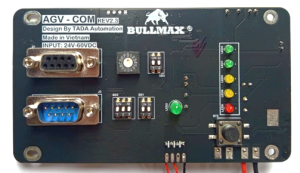
Model: TDA-AGV-COM.Rev2.3
Maker : Công Ty TNHH Tự Động Hóa Tada
The new protocol, referred to as the “NEW version” is characterized by the addition of only the CANopen functionality compared to the old version. The rest remains unchanged.
CAN open will be implemented in products manufactured since April 2022, and for older versions, the feature can be enabled through firmware upgrades..
BMU (Battery Monitoring Unit)
| no. | type | explanation | application | How to set / note | |
| ⑥ | D-SUB 9Pin(Female) (CAN) | CAN Comm. port
(Refer to the pin mapping specifications for details) |
When ‘ⓑ Communication ON,’ transmission and reception are enabled.
CAN communication is available without additional configuration, excluding ⓒ,ⓑ,ⓔ below. |
||
| ⓑ | D-SUB 9 Pin (Male) (SERIAL) | RS232 / RS485 / RS422
(Refer to the pin mapping specifications.) |
When ‘ⓓ Communication ON,’ transmission and reception are enabled. | ||
| After changing the ⓒⓓⓔⓕ select switch position, it is imperative to turn the power OFF and then ON. | ⓒ | Rotary | IP set
(COMM IP) |
Configurable from 0 to 15, use the indicated arrow
value on the switch as the address. |
* In hexadecimal format (0 ~ 9, A ~ F)
*”You can set addresses up to a total of 16.. |
| ⓑ | 2Pin | COMM ON/OFF | PIN1: Comm. ON/OFF
PIN2: Debug ON/OFF <Firm ware download mode> PIN1: OFF PIN2: ON |
* Comm. On set
ON : UP , OFF : DOWN |
|
| ⓔ | 3Pin | Termination Resistor set
(RT SET) |
PIN1 : for CAN
PIN2 : for RS422(RX Line) PIN3 : for RS485 or RS422(TX Line) *RT = Resistor Termination *note 1: In the case of RS422/485, using termination resistors is not crucial, but for CAN communication, it is strongly recommended and considered essential. *note 2 : If the user-side communication device has a termination resistor attached, the termination resistor of this device will be used. If the user-side communication device does not have a termination resistor, the termination resistor of this device will not be used either *note 3 : Refer to ‘1.6 Termination Resistor Usage’ in this manual. |
* Termination Resistor Configuration
(note): ON : UP , OFF : DOWN note : internal termination resistor = 120Ω |
|
| If you use RS232C, all RT Switches have to be turned off. | |||||
| ⓕ | 2Pin | Comm. selection
(SERIAL TYPE) |
PIN1 : RS232 / RS485 PIN2 : RS485 / RS422 | *Comm. Type settings
* * * * * * * * * * (Note) ON : UP , OFF : DOWN * For SERIAL communication, one of the options mentioned above should be selected. *Simultaneous use of SERIAL and CAN is possible. |